Details
Solution type
To manage peaks in district heating and district cooling, one method is to store hot or cold water in insulated tanks to use when demand is increasing - so called thermal energy storage (TES) . In this way, no additional production units must be started, which will significantly reduce the environmental impact and reduce costs. This article will present an overview and the basic principles for thermal energy Storage.
Introduction
Thermal energy storage (TES) is one form of energy storage. In this case, a material gains energy when increasing its temperature, and loses it when decreasing. Taking advantage of this property makes it possible to use different materials with different thermal properties and achieve various results which can lead to different thermal energy storage applications (e.g. heating and cooling). TES can help to balance energy demand and supply on a daily, weekly and even seasonal basis, presented in thermal systems. TES can also reduce peak demand, energy consumption, CO2 emissions and costs; while also increasing the overall efficiency of energy systems (Dinçer, 2011).
The most common application for thermal energy storage is in solar thermal systems. However, due to its wide range of benefits, TES is used in many other applications as well - such as those found in CELSIUS demonstrators; to store heat in building structures, to couple waste heat and district heating systems and to couple heat pumps and combined heat and power (CHP) generators in district heating networks.
The increasing use of renewable energy sources during the last two decades has increased the importance of research and development of energy storage systems. Intermittent sources such as wind, solar or tide do not always generate energy at the same rate as the energy in cities consumed. This switch, from energy systems governed by traditional fossil fuels to systems with high penetration of renewable energies, introduces load imbalances between supply and demand.
The importance of TES in future energy systems with high amounts of intermittent renewable energy sources is due to the fact that half of the total final energy consumption worldwide can be attributed to heat (International Energy Agency, 2013). Thermal energy storage is much cheaper than electricity storage and it has a high potential of integrating intermittent RE sources such as wind and solar into the heating or cooling sector, via e.g. heat pumps or electric boilers (Sandia Energy Storages Systems, u.d.). TES provides several benefits to heating and cooling networks (DHC), including reducing peak thermal demands, increasing the efficiency of the system and integrating other heat sources such as industrial waste heat or seawater.
The application of thermal energy storage with renewable energy sources, waste heat, or surplus energy production can replace heat or cold generation from fossil fuels, reducing greenhouse gas (GHG) emissions and reducing the need for the thermal power capacity of the generators. “In Europe, it has been estimated that around 1.4 million GWh per year could be saved— and 400 million tons of CO2 emissions avoided—in the building and industrial sectors by more extensive use of heat and cold storage” (IEA-ETSAP and IRENA, 2013).
In CELSIUS, thermal energy storage systems are used to integrate waste heat sources, for example, the heat coming directly from a waste incineration plant in Rotterdam. Other waste heat sources in the project are a ventilation shaft in the London Tube and the exhaust heat in one electrical substation in London. In Cologne, Germany, heat is being recovered from the sewage system. Another project using short-term thermal storage is the demonstrator GO1 in Gothenburg, which uses the thermal capacity of the building as a storage medium in order to better manage the heat supply and demand imbalances.
Basic Principle and Thermal Energy Storage Methods
Basic Principle
The basic principle is the same in all TES applications. Energy is supplied to a storage system for removal and use at a later time. What mainly varies is the scale of the storage and the storage method used. The process of storing thermal energy can be described in three steps, referred to as a cycle. These steps are charging, storing and discharging. The storage cycle applies to sensible, latent and chemical storage; the differences between these methods are the material, the temperature of operation and a few other parameters. Water, for instance, is the more commonly used medium for sensible storage, but this varies depending on the application (Dinçer, 2011).
Another important aspect to know about TES systems is the length of time the energy is stored. Depending on the duration of the time that the heat or cold is stored, TES is usually classified as short or long term (seasonal storage). A buffer tank can be used daily to reduce the peak power of heat generators in DHC systems. The heat or cold stored in the buffer tanks provides part of the thermal demand presented commonly during the mornings or evenings in the thermal systems, which reduces the thermal power of gas boilers or CHP plants. This case can be classified as short-term storage, but thermal energy storage can be used for longer periods of time (weeks or months) as well. To tackle seasonal temperature variations, heat can be collected during the warm summer, for example in large water ponds (e.g. 60,000 m3), using solar thermal collectors. It can then be stored and later released to dwellings in the winter (Furbo., 2014). Conversely, a cold store can be charged in winter and then provide cooling during summer.
TES can also be classified into decentralized and centralized TES. Centralized energy storage can be found in district heating and cooling networks, large industrial plants, combined heat and power plants and renewable energy power plants - while decentralized TES are found commonly in domestic and commercial buildings, where it’s used to store solar energy for hot water and space heating applications.
Methods of Thermal Energy Storage
TES applications may use different material properties to achieve energy storage. According to the thermal mechanism used to store energy, TES can be classified into three types: Sensible (e.g., water and rock), Latent (e.g., water/ice and salt hydrates) and Thermo-chemical reactions (e.g., chemical reactions and sorption processes). Sensible storage happens when the temperature of a material is raised or lowered, whereas latent storage occurs when the phase of a material is changed (solid to liquid or liquid to vapour) without a change in temperature. Both mechanisms can occur in the same material. The third mechanism, a chemical reaction or a sorption process, takes place on the surface of a material. In all cases, heat can be either absorbed or released from the material.
Motivations for Implementing Thermal Energy Storage in District Heating and Cooling Systems
District heating and cooling (DHC), together with thermal energy storage (TES), are potential technologies for the integration of renewable energy and the reduction of CO2 emissions in the European Energy Sector and the interaction and development between both technologies is of significant importance. DHC and TES, together with for example hybrid systems and heat pumps, are identified as cross-cutting technologies by the renewable heating and cooling platform - meaning that are key enabling technologies for fully decarbonizing the heating and cooling sector by 2050. TES can maximize the benefits that DHC provides to the energy system.
One of the major challenges for future energy systems is to overcome the mismatch between supply and demand caused by the increasingly strong deployment of intermittent renewable energy sources. By interlinking the electricity sectors and the heating and cooling sectors, and by deploying thermal storage, the mismatch and intermittence problems can be addressed. These new operational constraints for future energy systems also require the development and deployment of energy management tools in both electric and thermal networks. This intelligent management is achieved with new information and communication technologies and a new smart energy system approach.
The way TES contributes to solving the mismatch between supply and demand is by providing management capabilities to the system. TES can also help to integrate intermittent RE into the DHC systems and, furthermore, by adding TES into DHC systems (with CHP and waste heat), increase the energy efficiency of the whole system.
The effective integration of TES into heating and cooling energy systems can lead to benefits such as (Dinçer, 2011):
- Reduction of energy consumption
- Increase energy efficiency
- Increased energy security
- Increased energy reliability
- Reduction of energy costs
- Reduction of GHG emissions
In order to achieve these benefits, thermal energy storage should be used properly; for example for balancing thermal supply and demand, integrating renewable energy, or recovering waste heat.

Storage capacity vs temperature for sensible, latent and thermochemical TES (International Energy Agency, 2013)
Balancing Supply and Demand
The most common example of load balancing is in solar energy systems. The solar energy is stored during the day and used during the night or in the early hours of the day, in individual households or at a district heating level. Thermal Energy Storage in district heating and cooling systems serves as a reserve of thermal energy, which can be used to supply heat or cooling load in times of peak demand or in times of high electricity prices - when heat is produced through electric heaters or heat pumps. When heat is produced through CHP plants and electricity prices are low, on the other hand, the heat demand can be covered by using TES.
In the upcoming years, if CHP plants are required to operate, because there is not enough renewable energy power in the system, and there is no heat demand at that moment, TES allows the CHP plant to operate, recovering the heat at the same time (See the CHP flexibility through TES video). These differences between supply and demand can be smoothed out by TES, which can provide several benefits for the systems; such as reducing the size of generators' capacity, reducing thermal supply costs and integrating other hot/cold sources -whose availability varies over time (Dinçer, 2011). The problems of mismatch between supply and demand during individual days can be handled by TES. This also works for longer periods of time, for example within months (seasonal storage). During individual days, TES can be operated in several ways (Load Shift & Save®, u.d.):
-
Full Storage
Thermal energy is generated at night when electricity is both plentiful, less expensive and uses less primary energy than in the day. Electricity from wind power can also be integrated during these times of the day.
-
Part Storage Load Leveling
Thermal energy is generated during daytime peak hours to supply thermal loads when electricity loads peak (Peak Shaving), which makes electricity prices expensive.
-
Part Storage
Thermal energy storage reduces the peak electrical demand, helping both the end user and the utility.
The RHC-platform identifies TES as a potential technological solution for the time mismatch between renewable energy sources and thermal demands, establishing the following key priorities (European Commission, Joint Research Centre, and European Technology Platform on Renewable Heating and Cooling - RHC-Platform, 2011):
1. Storage systems for daily demand-supply matching
- Enable the exchange of thermal energy at the district level between supply and demand nodes at the building level (smart thermal grids), where the centralized and decentralized storage system can provide buffering capability of 1-7 days
- Optimize system performance by using cold storage in cooling and refrigeration applications
- Store heat decentralized in the form of heat-storing plastering material and storage walls
2. Storage systems for seasonal demand-supply mismatch for thermal energy needs
- Further develop large, centralized thermal storage systems, including UTES systems
- Bring to the market a seasonal heat storage system with an energy density 4-8 times that of water
3. Integration aspects of storage technologies
- The integration into energy production/supply systems, building elements, district systems and industrial applications should be prioritized. In order to achieve these goals, a high priority in TES must be set.
Research and development in thermal energy storage systems for both daily and seasonal demand-supply mismatch should have high priority in future district heating systems, in order to exploit as much of the benefits of this technology as possible.
Integration of Renewable Energy
TES in DH systems
In early district heating networks, from around 1800, the only two sources used to provide heat were coal and waste. Later, around 1930 (which is considered the start of the second generation of district heating networks), the first CHP plants were introduced to supply the heat. The introduction of CHP plants brought a reduction in temperature levels, leading to an increase in energy efficiency. This also opened up for fuels, such as oil, but it was not until 1980 that biomass was introduced as fuel for CHP plants. Renewable energy has finally started to become part of the district heating sources more recently (Rezaie, 2013). At present, cogeneration plants cover the majority of heat demand in district heating systems. Using biomass in CHP plants allows countries to significantly reduce their CO2 emissions when compared with the traditional heat supply of coal fired plants. This way, renewable energy can be integrated into the heating sector. This is the case for the Avedore Heat and Power Plant (link in wiki), where part of its primary energy comes from a variety of biomass sources, and its two storage tanks have a capacity of 44,000 m3 water combined (European Commission, Joint Research Centre, and European Technology Platform on Renewable Heating and Cooling (RHC-Platform), 2011)
TES in solar thermal hybrid DH systems
The overall thermal output in traditional district heating and cooling (DHC) systems can be improved by integrating renewable thermal energy resources. TES can be an ideal solution for the integration of, for example, solar thermal, geothermal and biomass sources. A smart implementation of TES contributes to enhancing the performance in DHC networks and can also reduce costs in such systems (European Commission, Joint Research Centre, and European Technology Platform on Renewable Heating and Cooling (RHC-Platform), 2011). Biomass, solar thermal and geothermal energy are the main renewable energy sources currently used as heating sources. These resources provide hot water and space heating for tens of millions of domestic and commercial buildings worldwide (First, 2009).
Modern renewables contribute only a small part of total heat production. This contribution, however, is gradually rising, and in some countries, e.g., Sweden and Iceland, renewable energies provide 60% of final energy consumption for heating purposes (First, 2009).
Amongst other things, heat pumps make it possible to provide geothermal-based space heating and hot water outside of volcanic regions. Heat pumps allow for the use of low heat sources from ground, air and water bodies such as lakes or rivers. It can also be used to recover waste energy from sewage or industrial processes in a very efficient way, by using electricity or heat to upgrade low intensity thermal waste energy into usable heat or cold. Moreover, heat pumps, together with TES, can increase the share of renewable energy produced when used as primary energy, power coming from wind or solar energy in the so-called Power-to-heat.
The following points summarize the progress achieved towards the integration of RE into the heating sector during the year 2014 (First, 2009):
- Storage systems have been demonstrated and are now available in some European markets.
- The use of bio-heat for CHP systems and hybrid systems in district heating and industrial sectors increased.
- 20 countries in Europe use renewables to feed district heating systems.
- The waste of wind energy in previous years (12% of wind power produced in 2011 and 21.8 GW in 2012) in China, led the government of that nation to promote the development of wind-to-heat projects in areas where conditions are suitable.
- A cornerstone of Danish energy policy is the combination of renewable energy with CHP and district heating systems.
- In a rising number of countries, renewable energy is considered crucial for meeting current and future energy needs.
- Denmark also aims to achieve 40% of renewable energy in heat supply by 2020. As one of the measures to achieve this goal, fossil-fuel fired boilers were banned in new buildings as of 2013.
See SUNSTORE4, in Marstal, Denmark and Energiebunker, in Hamburg, Germany, where thermal energy storage is used to integrate a variety of renewable energy sources in district heating systems.
Increase in Energy Efficiency
Another important benefit provided to the energy systems by using thermal energy storage is the increase in energy efficiency. Energy efficiency is achieved by storing heat (which otherwise would be released into the environment) and then using it when needed, e.g. in district heating systems. This way, less fossil-fuel is required and plant emissions are reduced, which leads to a reduction in product costs as well.
Useful waste or surplus thermal energy is available from many sources. Some examples are (i) hot/cold water drained to a sewer, (ii) hot flue gases, (iii) exhaust air streams, (iv) hot or cold gases or waste gases, (v) heat collected from solar panels, (vi) ground source thermal energy, (vii) heat rejected from the condensers of refrigeration and air-conditioning equipment, and (viii) the cooling effect from the evaporator of a heat pump (Dinçer, 2011).
However, TES alone cannot provide these benefits. It needs to be assisted by intelligent control systems and information and communication technologies (ICT) in order to contribute to better energy management, for example in recovering industrial waste heat. A good example of this is the demonstrator RO1, where the heat tank is managed with the help of IT infrastructure.
Another possibility to increase efficiency is in cooling systems when using TES together with chillers during the night (at an off-peak period), and due to the different ambient temperatures at which they work, chillers can enhance their performance. This leads to a reduction in the plant’s electric consumption. Also, the increase in the number of operational hours of the equipment reduces capital costs. Furthermore, by using this combination of technologies, the chiller needed capacity is as well reduced (Dinçer, 2011).
Short and Long-Term Thermal Energy Storage (Case Studies Outside CELSIUS)
Thermal energy storage can provide DH networks with different technical capabilities mainly in two different time scales; short and long-term energy storage. Peak Shaving and increasing the penetration of intermittent renewable energy sources through Power-to-heat technologies are some of these capabilities allowed with TES.
Short-Term Thermal Energy Storage
Thermal energy storage smoothens constraints between heat load (heat demand) and operation of boilers (heat generation), characteristically sized to cover daily peak load, or weekend heat usage, practical minimum boiler load or to time shift utilization of heat and electricity from combined heat and power plants (CHP) and/or to minimize the change of boiler operation.
Typical short-term storage is the displacement of hot/cold water from one hour to another via accumulator tank storage. Normally, these tanks have a vertical cylindrical form, made of steel and are often located near the main boiler plant. The volume of the tanks varies from a few hundred cubic meters to tens of thousands. There are two main types of tanks, pressurized and atmospheric (non-pressurized) tanks. Rock caverns can also be used as short-term displacement storages. The piping network itself is another form of short-term storage, used to smoothen constraints between heat load and heat generation in district heating systems. Other applications of TES are small tanks at the end-user side as example for domestic hot water, and the use of the buildings structure’s thermal inertia as heat storage in heating systems.
Other technical capabilities of TES are, for example, the use of storage during boiler maintenance works, the use of an emergency heat generator and the use of water reserve in case of major leakage. Sometimes the thermal storage also works as an open expansion vessel to maintain the static network pressure.
Integrated thermal energy storage into heating and cooling networks not only allows balancing the daily supply and demand but also provide the ability to manage electrical generation in CHP plants, thus allowing the generation of thermal energy at times when electricity is needed or when it is more profitable for the CHP plant. The flexibility given by TES to heat generation systems provides economic and technical benefits such as cheaper production of heat/cold, increase penetration of renewable energy into the energy generation mix and it can also allow to capture heat that otherwise would be wasted.
Real cases using short-term energy storage
Long-Term (Seasonal) Storage
Seasonal thermal stores have traditionally been tied to solar heat, allowing the surplus energy in summer to be displaced to the winter period, when demand is high and supply low. They are therefore designed to both provide sufficient capacity to absorb that surplus, and sufficiently low energy loss over time to be able to release a significant share of it later in the year.
Furthermore, in the context of a traditional district heating network, the ability to store thermal energy decouples the supply of electricity from the supply of heat. This is of importance when for example CHP plants are integrated into district heating networks, which would allow them to produce heat when the electricity price is high, as opposed to when the heat is needed.
A seasonal thermal store amplifies this effect even further by allowing CHPs to still produce both electricity and heat during the summer period, siphoning the produced heat for use during the winter months. An example of this can be found in Linköping (Sweden) as illustrated below, where an exceptionally large 3.000.000 m3 rock cavern store is charged (light blue) predominantly in summer and discharged (yellow) in winter.

Example of seasonal thermal discrepancy: solar gain versus heat demand. (E-hub. org, 2012)
Types of Seasonal Storage
Four types of large-scale or seasonal thermal energy storage are commonly used worldwide. The four storage concepts shown in the figure include tank and pit thermal energy storage (TTES and PTES), borehole thermal energy storage (BTES) and aquifer thermal energy storage (ATES). Two less common types, Cavern Thermal Energy Storage (CTES) and Phase Change Material Energy Storage (PCMES) are briefly mentioned.
With the exception of snow storage, latent and thermochemical storage methods at a seasonal scale are still in various stages of development and will most likely be significantly more expensive than sensible thermal storage systems. And although storing biomass and other chemical carriers for later use in CHP plants could also be considered seasonal thermal storage, this section specifically deals with market ready latent storage systems that use highly common, low cost materials.
Thermal stores of these types can be built at a very large scale, which is important in providing significant thermal storage capacity at a relatively low cost. As a larger store will lose less heat over time, therefore providing a cost benefit when compared to the same capacity spread over many small stores, as well as allowing for greater stratification, concentration will be beneficial.
Real case using Long-term (seasonal) energy storage
SUNSTORE4, in Marstal, Denmark
Current Status of TES Technologies, Potential, Barriers and Costs
The implementation of thermal energy storage brings several benefits to the actual and future DHC systems but the TES market varies considerably, depending on the application fields and regions. The IRENA and ETSAP organizations described in their report “Thermal Energy Storage - Technology Brief the potential of implementation of TES systems (IEA-ETSAP and IRENA, 2013).
TES Technologies Current Status
One of the most common technologies installed today is domestic hot water tanks. Other technologies, such as ice and chilled water storage, play an important role in several countries, including Australia, the United States, China and Japan, as utilities seek to reduce peak loads and consumers seek to lower their electricity bills. UTES systems are frequently found in Canada, Germany, and many other European countries (IEA, 2011).

Energy Storage Technologies: current status and typical locations in today’s energy Systems. (IEA, 2014)
In the installed capacity of TES is difficult to address an exact quantity of the installed capacity of thermal energy storage projects worldwide. In the Nordic countries there were more than 100 storages in the year 1993 most of them smaller than 2 500 m3, about thirty of them were between 2 500 and 20 000 m3 (Petersen, 1993). In Sweden, about 70 storages were in operation by the end of 1990s, where 39 were atmospheric, the majority of those were below 10 000 m3, while the largest was 40 000 m3 (Lindberg, 1998). In Denmark, large-scale pit storages are succeeding during the last years in the solar thermal district heating field. For example, the Dronninglund pit storage accounts for 61,700 m3 and the new Marstal-2 project, will account for 75,000 m3 (Furbo., 2014).

List of large-scale Solar Plants in Denmark Pit Storage Thermal projects. (Frey, 2014)
Some installed capacities in the USA by the year 2011 are: Ice storage (commercial buildings and district cooling) 1000 MW, Cold-water storage (district cooling) 355MW and electric thermal storage (heating) 1000 MW (IEA, 2014).
With the Interactive Thermal Energy Storage Map, some projects with thermal energy storage in Europe can be tracked.
Market Maturity
There are several factors to consider when analysing the market opportunities of Thermal Energy Storage. Some of them are the maturity of the technologies, their costs, and the application fields and region.

Maturity of energy storage technologies
Technology availability and market maturity
More complex TES technologies (TCS and PCM) need to rapidly overcome technological, manufacturing, quality and production issues in order to reach the market, allowing them to be mass produced bringing down costs and making them affordable and widely available for end-users. This needs to happen for example to technologies like thermochemical heat storage for space heating and cooling, as well as the solar heat pump and chiller, which even in 2014 are still struggling to reach the market (SaltEx).
However, there are already some TES technologies in the commercialisation stage (mainly sensible storage) as pit storage, cold water storage and UTES. Technologies used in CELSIUS (e.g. hot water tanks and storage within the mass building) belong to sensible storage type of storage. There are some others, which are approaching this maturity stage but are still in the demonstration and deployment stage, such technologies are molten salt, ice storage, and residential hot water heaters with storage. According to the Technology Thermochemical storage is the less mature technology, and it is still in the research and development phase (IEA, 2014).
Opportunities, barriers and costs of Thermal Energy Storage
The IRENA and ETSAP organizations described in their report “Thermal Energy Storage - Technology Brief” the potential for implementation of TES systems (IEA-ETSAP and IRENA, 2013).
- In Europe it has been estimated that around 1.4 million GWh of energy per year could be saved in the building and industrial sectors by more extensive use of heat and cold storage.
- The rate of construction of new buildings in the building sector is around 1.3% per year and the renovation rate is 1.5 % (integration of TES is easier during the construction phase)
- An estimation of the European potential in TES development is based on the implementation rate of TES in buildings at 5%
- It is estimated that developing countries can have a higher penetration since they present high rates of new building construction
- Co-generation is associated with the building stock and has a rate of implementation of 10.2%, while implementation of TES in these systems is assumed to be 15%.
- In the industrial sector, about 5% of the final energy consumption is assumed to be used by TES installations
- The use of industrial waste heat is expected to grow since the price of fossil fuels will rise and energy efficiency will be the key of competitiveness
- A driver sector for TES can be concentrating solar power (CSP), where almost all new power plants are equipped with TES, mostly based on molten salt
- The expansion of TES technologies is expected to be significant in Europe and Asia (particularly in Japan) and somewhat lower (50%) in the United States
- The global potential is estimated at approximately three times the European potential
Besides the potential of TES technologies, TES also face some potential barriers like the ones listed below (IEA-ETSAP and IRENA, 2013).
- Market entry and costs
- Material properties and stabilities, in particular for thermos-chemical storage (TCS)
- Each TES need a specific design, boundary conditions and requirements
- Research and development (R&D) activities focus on all TES technologies. Most of such R&D efforts deal with materials (i.e. storage media for different temperature ranges), containers and thermal insulation development.
- More complex systems (i.e. PCM and TCS) require R&D efforts to improve reacting materials as well as a better understanding of system integration and process parameters

State of Development, Barriers and Main R&D Topics for Different TES Technologies (IEA-ETSAP and IRENA, 2013).
Some TES technologies are less mature than others, therefore they are placed still in the materials research stage. However, sensible TES is more developed, and its cost is not anymore an issue.
Investment Costs of Thermal Energy Storage
The estimated cost of the thermal energy systems considers storage material, operation costs, and technical equipment for charging and discharging the storage device. Sensible storage is a rather inexpensive technology and the cost of it decreases as the size of the storage media (mostly water) increases. An important element of the system is the insulation, and it might be a significant part of the cost. The aim of the development of pit storages in Denmark is to bring down the investment cost per m3 of water below 35 €/m3 (Schmidt, 2011). Most systems in the graph consist of a 5,000-10,000 m³ water container with energy content between 70-90 kWh/m³ and investment costs between 50-200 €/m³ of water equivalent. This represents a specific investment cost from 0.5-3.0 €/kWh.
Using TES in a smart way can help to save money. In countries like England with high differences between high-peak and low-peak electricity tariffs, TES allows CHP units to follow the electricity prices. Therefore, integrating thermal energy storage into district heating networks contributes not only to system operations but also to the economics of these networks. Large plants also cost less per unit of energy output, whereas individual boilers and micro CHP have to be sized for the full theoretical loads of the buildings and are also disproportionately costly (Andrews, 2012).
In summary, TES can also help to incorporate a variety of resources such as biomass, geothermal, solar and waste heat in DHC networks. TES can also be applied and contribute to absorbing surplus power from intermittent renewable energy sources (e.g. wind, solar) by generating heat or cold using electric devices (power-to-heat or power-to-cooling) during off-peak hours, for later use during subsequent peak hours. TES also improves the recovery process of waste heat from diverse sources, ranging from industries to sewage water, some of which would otherwise be discharged and wasted into the environment, during off-peak hours and seasons. The introduction of TES in some energy systems is starting now. However, TES technologies need more visibility in the energy system. TES capacity is not well evaluated, and its current status and deployment are not well known. Research and deployment activities need to keep going in several fields on TES, only this way, the take off of TES technologies can be accelerated.

Investment cost per m3 water equivalent [€/m³] (Schmidt, 2011).
CELSIUS Demonstrators with Thermal Energy Storage
RO1 The Heat hub
Demonstrator Overview
The district heating system in Rotterdam was established in 1948. At present it involves five companies, either in a producing or transporting role, or distributing heat to individual customers. E.On operates the RoCa CHP plant (and the recently decommissioned Galileïstraat CHP plant), which partially supply the oldest sections on the north bank of the Meuse river, operated by Eneco. Local gas fired peak plants provide additional capacity. On the south bank, CELSIUS partner Warmtebedrijf (or Heat Company) Rotterdam operates a 26 km (approx.105 MWth) transport network with booster stations, connecting the Rozenburg waste incineration plant in the west with various distribution areas eastward, operated by Nuon, as well as with the north bank network through an interconnector drilled beneath the river. A recently completed second set of transport pipes operated by Eneco connects additional heat exchangers at the waste incineration plant directly to the north bank network.
Brief description
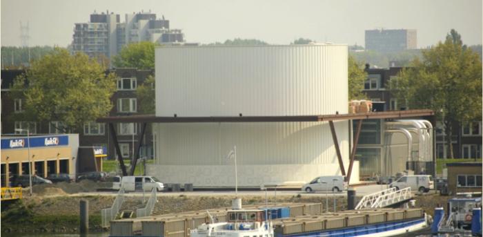
The northbound connector is part of CELSIUS demonstrator RO1, the Heat Hub (Brielselaan, #4 in the figure below), which has been completed in Q4 2013. It not only connects the networks on both sides of the Meuse river but also augments the system with a 5.000 m3 water-based and thermally stratified storage buffer, at a strategic location away from the production facilities.

Heating network connection of RO1-The heat hub.
The heat hub has three key features:
- The heat hub acts as a distribution station and it connects the existing district heating systems in the south and north of Rotterdam.
- The heat hub has a well-insulated buffering tank. The capacity of the buffer is 185 MWh and has a (dis)charge capacity of 30 MWtth. The buffer provides further optimization opportunities and it can serve as backup capacity.
- The heat hub is the central point of the IT infrastructure, for better forecasting and heat balancing, a smart ICT system is under development. This ICT system is a crucial element in the further optimisation of heat sources, buffers, new connections and pumping stations in the waste heat transportation infrastructure of Warmtebedrijf Rotterdam and the entire district heating system.
The heat hub is designed to deliver 70 MWth at a temperature difference between supply and return of 50°C and a flow of 1200 m3/hr. The maximum supply temperature is 120°C. This heat is transferred to the existing district heating network operated by Eneco on the north bank, by means of two plate heat exchangers (secondary side). Furthermore, Warmtebedrijf Rotterdam has the ability to store heat at the primary side of the heat hub by means of an atmospheric heat buffer. The heat buffer consists of a hot (approximately 98°C) and a relatively cold layer (approximately 60°C) and has a heat storage capacity of approximately 185 MWh at a temperature difference between the cold and hot layer of 30°C.
The main components of the heat hub are:
- A buffer loading and unloading pump;
- Two return pumps are needed to transport the return water back to AVR (heat supplier);
- Two plate heat exchangers with a throughput of approximately 35 MWth each. These heat exchangers are the physical separation of the newly built primary side and the existing secondary side (on the north bank, operated by Eneco);
- Two secondary pumps are needed to transport the return water of the secondary side through the plate heat exchangers to the hot supply line of the secondary side.
The heat is measured and calculated by auditing flow meters and temperature sensors. Except for the heat buffer itself, all equipment and main components are installed in a dedicated and closed building structure adjacent to the buffer.
As part of the CELSIUS project, several parameters and key performance indicators (KPI) from all demonstrators are currently being logged and monitored. More detailed information about the KPI's from the RO1 can be seen in the following link:
CO1 Waste heat recovery from sewage
Heat is covered from sewage water through heat exchangers coupled with heat pumps and heat buffer tanks. The company Rheinenergie has installed heat pumps together with gas-fired boilers in order to supply the space heating and hot water demands of three different schools in Cologne Germany.

Control display at CO1 Wahn (plant visit in November 2014) Photo: Aldo Perez (Olsson Ingvarson L.C., 2008).
Brief Description
One of the three demonstrator sites is the plant built in the district of Wahn in Cologne, Germany. The plant is operating since October 2013 and supplies space heating and hot water to a school located in the above-mentioned area. The heating generation system consists of a 1 MW gas-fired boiler and a 200 kW water-water heat pump, which uses as low heat source water from the sewage. A stratified buffer tank with a capacity of 3.82 m3 balances and manages the heat supply and demand of the system. The hot water produced by both generators is pumped to a buffer tank and it is short stored there. Later on, the hot water is pumped from the buffer tank to the distributors of the system. One distributor supplies the sports hall of the school, while the other distributor supplies the rest of the school buildings.
Buffer tank
The stratified tank is divided into five different layers, each of which has different temperatures. The hot water generated by the boiler goes to the top layer, which supplies the school distributor. The next layer from the top to the bottom has two outlets. One of them goes to the sports hall distributor, while the other is still without connection, remaining free in case of an expansion of the heating system. One layer below is the preheating layer, where the heat pump supplies hot water up to 55°C and the feeding of the boiler comes from this layer, too. The next layer is considered the thermocline, since the mixture level of water is higher and therefore, no pipe system is connected here. Finally, the bottom layer is the coldest and it is here where the return pipes of both distributors are connected. The return pipe of the hot side of the heat pump comes also from this layer.
The temperatures inside the buffer tank are monitored by four temperature sensors spread along the height of the tank. The temperatures are measured every 15 minutes and together with other values are saved and sent to the onsite display. The buffer tank plays an energy management task, as from there the hot water is distributed more efficiently to both distributors, maintaining always certain temperatures according to different variables. It also allows the heat pump to preheat the water up to 55°C, and in case the heat demand exceeds this temperature, the control system sends a signal to turn on the boiler in order to heat the water in the buffer tank further. Heat buffer temperatures and other monitored parameters as well as key performance indicators (KPI) can be plotted with the help of the parameters and KPI calculation tool.

Inlets and outlets of the buffer tank at CO1 Wahn (adapted diagram from the buffer tank data sheet).
Energy buffer tank temperatures and heat generators' frequency operation
In January the daily average temperatures inside the heat storage are the highest in the year. Heat peak loads are identified between 4:30 and 6 am and 13 to 14 hrs. Between 4 to 11 am temperatures maintain constantly high. And between 18 to 3 am temperatures maintain constantly low.
The hours when both generators are more frequently operating match with the high temperatures in the heat buffer tank. They operate from 4:30 to 7:00 in the morning approx. and from 12:30 to 13:30 approx. Both generators cover the heat demand peaks of the day. The heat pump is after midday operating more frequently as it covers the heat base load, while the boiler operates only when heat demand peaks.
As part of the CELSIUS project, several parameters and key performance indicators (KPI) from all demonstrators are currently being logged and monitored.
GO1 Buildings for Short-term Storage
Storage of thermal energy in the building structure is being tested in a Celsius demonstrator “GO1” in Gothenburg. The building can be “loaded” and “unloaded” with heat by installing equipment that allows the district heating network operator to adjust the amount of heat delivered to a building at certain times of the day, thus contributing to shift heat demand from peak hours to hours with lower heat demand.
Brief Description
Various concepts can be used for loading and unloading the building structure. In the demonstrator GO1, the outdoor temperature sensor is manipulated in a way that the district heating substation in the building supplies more or less heat to the building system than it would otherwise do, thus loading more energy onto the building or unloading it.
The ability to store heat in a building is based both on the thermal characteristics of the building materials, i.e. their capacity to store heat and the acceptance of slight variations in indoor temperature. In a building that is heated to the desired indoor temperature and at steady-state, i.e. the heat losses to the surroundings are balanced by the heat provided by the district heating via a space heating system, heat can only be unloaded by temporarily reducing the heat supply. Once the heat supply is reduced, the indoor temperature will start to drop, but when it does, all materials (walls, floor structures etc.) will start to release their retained heat. The retained heat will make the indoor temperature drop only slowly.
The GO1 technology takes advantage of this fact and, if the technology is applied correctly, the residents shall not even notice the small changes in indoor temperature. In order to reload the heat that was “borrowed” from the building during peak hours, the district heating operator can increase the heat supply slightly during other parts of the day, thus maintaining the heat balance over the long run. In practice, the heat supply changes to the buildings are achieved by manipulating the outdoor temperature sensor signal. This way, no adjustments are needed in the buildings’ control system; they are only “made to believe” that the outdoor temperature is either higher or lower than it actually is.
Feasibility Tests
The CELSIUS demonstration of this technology is expected to start operating during the winter of 2015/2016. There are thus no results yet from this demonstrator. However, Göteborg Energi has performed small-scale experiments and tests of the technology before; results from which are available. One study focused on field measurements of time constants (Olsson Ingvarson L.C., 2008). In previous feasibility studies of the potential of this technology on the system level, the average time constant was assumed at 100 hours.
The field tests confirmed that this was no underestimation; most buildings had time constants well above that. Even wooden buildings had an average time constant of 102 hours. The preliminary results showed that the daily load variations at the system level could be eliminated using the thermal mass of the building as short-term heat storage. Using the thermal mass of the building might be more cost-efficient than constructing large separate hot water accumulators. Göteborg Energi has tested the technology in real buildings in order to evaluate the effect on indoor temperatures, DH return temperature, achieved heat power reduction and heat power response, as well as to find optimal settings for the modification of the outdoor temperature signal. Evaluations of results from measurements and tests with different test cycles on a number of buildings showed that: (Elebo J., 2013) The indoor temperature dropped by 0.18-0.8 °C, which was not more than natural variations. The heat power reduction was in the range of 10-13 W/m² or 17-21 W/m² building area, depending on the induced change in outdoor temperature (up to ±7 °C from the actual outdoor temperature was tested). The larger induced change gave a larger power reduction. Other tests by Göteborg Energi have also shown that the changes in indoor temperature are small and should not affect the residents’ perceived comfort. However, the heat power reduction was found to be smaller than the theoretical value (40-80 %). One explanation could be that well-functioning thermostats counteract the effect of reducing the heat supply since they do their best to maintain the indoor temperature. From a DH perspective, the return temperature from buildings was affected when applying the technology: it was reduced somewhat during loading and increased somewhat during unloading.
LO1 and LO2 Short-term Thermal Storage
The London Underground’s mid-tunnel ventilation shaft and UK Power Network’s electricity substation have been identified as sources of waste heat that could be utilized within the local Bunhill Heat and Power Network. This demonstrator will look at how these sources of waste heat can be captured and integrated into this local district heating system. It will also consider how this could form the beginning of a strategically important energy hub that will allow the subsequent extension of the heating system in the area. The second part of this demonstrator will be the integration of a thermal store to help with energy balancing in the area. This demonstrator will develop an understanding of how waste heat can be economically captured and utilized within a local district heating system and how a thermal store can help with the balancing of both surplus electricity and heat within their respective networks.
The demonstrator in Islington, London is still under construction and it is planned to start operating in 2016.

Hot Water Thermal Storage at Islington DH Network. Capacity: 130 m3. Photo: Aldo Perez
Energy storage interactive tools
Thermal Energy Storage in Europe
The following link contains an interactive map of Europe where most of the Thermal Energy Storage facilities can be found. The idea of the interactive map is to easily find a specific project mainly within the participant countries in Celsius. Each registered project in the interactive map contains basic information about the facility e.g. Thermal Energy Capacity, Size of the Thermal Energy Storage, Energy Generation Technology, Storage Material, Fuels used, etc. A link to the main internet page of the project can be sometimes found.
At the moment, the interactive map contains projects in the countries: Austria, Denmark, Germany, Italy, Netherlands, Poland, Sweden, Switzerland and the UK. The interactive map will continue to update, by adding new projects in the upcoming years.
Interactive Thermal Energy Storage Map
Other energy storage technologies
Economic Tool
The economic tool was developed by the Cologne University of Applied Sciences. It allows the user to calculate the cost of different types of thermal energy storage. The user should provide basic parameters such as type of storage, size, technology, etc. The tool calculates approximately the costs of thermal energy storage depending on the input parameters provided by the user.
At the moment it is only available in German: Economic Tool for Energy Storage
Parameters and KPI'S Calculation tool
The parameter and KPI calculator is a graphical user interface (GUI) that allows the user to plot the values of the desired parameter (e.g. temperatures in the heat storage, energy produced by heat generators, electricity consumption, gas consumption, etc.) for a certain period of time. It is also possible to request the yearly KPI'S (e.g. CO2 reductions, energy efficiency, surface area supplied by the demonstrator, etc.) or even to request a KPI calculated in a desired period of time.

Period data hourly basis+ KPIs selection 2014

Line Graphs with period data on hourly basis.

Graphical User Interface (GUI)

Subplots with period data on daily basis

Subplots with period data on a monthly basis.
References:
- Andrews, D. R.-G. (2012). Background report on EU-27 district heating and cooling potentials, barriers, best practice and measures of promotion. European Commission, Joint Research Centre. Retrieved from https://setis.ec.europa.eu/system/files/JRCDistrictheatingandcooling.pdf
- Dinçer, I. &. (2011). Thermal energy storage systems and applications. Hoboken, N.J.: Wiley.
- E-hub. org. (2012). Energy capture, storage, control and delivery within districts.
- Elebo J., P. D. (2013). Evaluation of buildings’ suitability as thermal energy storage in a district heating system. Gothenburg: Department of Energy and Environment. Chalmers University of Technology.
- European Commission, Joint Research Centre, and European Technology Platform on Renewable Heating and Cooling (RHC-Platform). (2011). 2020-2030-2050, common vision for the renewable heating and cooling sector in Europe: European technology platform on renewable heating and cooling. . Luxembourg: EUR-OP.
- First, G. S. (2009). Renewable Energy Policy Network for the 21st Century. Paris: REN21.
- Frey, J. (2014). Large Scale Solar Heating. Gleisdorf SOLAR 2014, Jun-2014.
- Furbo., S. (2014). Smart Heat Storage for solar heating systems. IEA.
- IEA. (2014). Technology Roadmap - Energy Storage. IEA. Retrieved from https://www.iea.org/reports/technology-roadmap-energy-storage
- IEA-ETSAP and IRENA. (2013). Thermal Energy Storage / Technology Brief.
- International Energy Agency. (2013). World Energy Outlook Special Report.
- Lindberg, B. (1998). Statusrapport trycklösa hetvattenackumulatorer. Svenska fjärrvärmeföreningen, FOU1998:21.
- Load Shift & Save®. (n.d.).
- Olsson Ingvarson L.C., W. S. (2008). Building mass used as short term heat storage. Reykjavik: The 11th International Symposium on District Heating and Cooling.
- Petersen, H. L. (1993). Korttidslagring af varmt vand i tanke over jorden. Dansk fjaernvaermevaerks forening.
- Rezaie, B. (2013). Assessing District Energy Systems Performance Integrated with Multiple Thermal Energy Storages. University of Ontario Institute of Technology.
- SaltEx. (n.d.). SaltEx. Retrieved from http://saltxtechnology.com/
- Sandia Energy Storages Systems. (n.d.). Retrieved from https://www.sandia.gov/ess-ssl/
- Schmidt, T. M. (2011). Large-scale heat storage. Eurosolar.
Related Celsius content:
Webinar: Seasonal and short-term storage
Strategies for decreasing peak loads and energy use
Webinar: Using buildings as thermal energy storages